
Pipe 8: The a-pipe, and multiple slices
Pipe 8: The a-pipe, and multiple slices
Together at last!

Scouting ahead
Let’s start with an overview of the a-pipe. You have seen the e-pipe, and this is quite similar, just a little smaller:
The a-pipe is the lesser, second part of the digest slice.
The e-pipe had more to do because it processes 5 of the digest bits and it is where the kw data bits enter. It calculates a new e-bit as its output, and copies some of the other bits do different output positions.
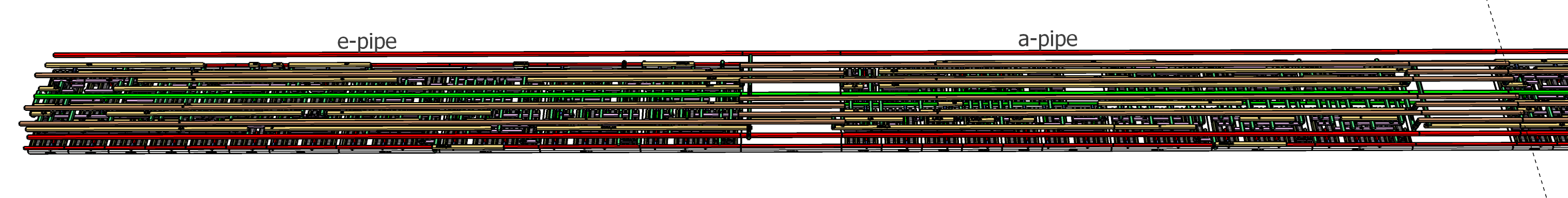
The a-pipe operates mostly on just 3 of the 8 digest bits. It generates a new a-bit and copies three inputs to different outputs.

The end of the a-pipe will be positioned in front of the e-pipe of the next stage of the digest, but actually most of the outputs of the a-pipe will be carried above the e-pipe and come back down to be inputs to the next stage’s a-pipe.
Latches and First Logic
The a-pipe needs fewer input latches than the e-pipe
but they are arranged in a similar way around the clock drivers. There are just 6 latches. The a, b, and c inputs feed a majority-of-3 circuit, while 3 a-rotation inputs feed the two XOR2 circuits.

There is an es1 input from the e-pipe of an adjacent slice but it is not latched since the source is part of the current stage.
Yes, that is an unused space about the size of a latch, the layout does not offer a way to improve by using it, at least not if we use standard cells. In practice, the empty spaces are useful for physical functions like capacitance or substrate bias connections. EDA tools generate these automatically wherever they can, after the logical cells have been placed and wired. Those physical functions are essential so a small fraction of “logicallly empty” space is inevitable.
Add it up
There are three full adders, one less than the e-pipe requires, which reflects that there are fewer input signals to be combined.

In both the e-pipe and the a-pipe each of the adders each combine 3 inputs and pass on 2 outputs, so they reduce the signal count until the final adder is reached.

Only the last of the adders needs to participate in a carry across all 32 slices. The prior adders feed forwards into that last stage even if they contribute a carry sideways to the adjacent slice. For example, the aCarry0_out from the first adder you can see feeds forward to the second adder of the neighboring slice, and the aCarry1_out from the second adder will feed into the B input of the adjacent third adder.

This forwarding allows all the carries to roll up into a single parallel carry in the final adder. A similar feed-forward happens in the e-pipe. The final stages, generating the e and a outputs, will be the only adders justified to have a carry-lookahead solution to mitigate the stage latency. This arrangement minimizes latency and overhead due to carries.
I welcome discussion of the open section of the post, you can add comments to the Table of Contents for Pipeline post if SubStack will not allow your comments here. Thanks!
Thank you for supporting this blog.
On to the next stage
The a-output is the end of the stage.

There is another blank space we will use for buffering the rotation signal and for carry lookahead, then to the right the e-pipe of the next stage begins.

Outputs from the a-pipe will mostly swap up to the M4 level to pass over the next-stage e-pipe, while signals from the e-pipe, out of view to the left, have been passing above the a-pipe and now swap down from the M4 level to be used as e-pipe inputs on the next stage.
Howdy, neighbor
It is time to start joining slices sideways.

A slice, with both the e-pipe and the a-pipe, aligns exactly

to a neighbor and we repeat that to create a bundle of 4 slices.

The details show the forwarded carries connect at the adjoining sides of the slices

and the signals connect forward and sideways through the section between the stages.
The pause that refreshes
I choose to leave a rail nominally empty between groups of 4 slices, let’s call it a “median” since it looks like a median on a highway.
This will not remain empty. The carry-forwards will cross that median, but more importantly the clock circuitry will be in the medians and what remains “empty” will be used for capacitor cells that improve power distribution and reduce low voltage droop. The less droop there is the lower the voltage can be, which has a squared benefit on energy per operation. The size of the chip will increase slightly but it is likely to be more efficient.
Yah, the medians should have been drawn with sideways connections. An exercise for the reader! Not very interesting, mostly just stretch an M1 wire between adjoining carry out-in pairs.

The groups and metdians are repeated up to 32 slices arranged as 8 bundles of 4
My drawing software struggled a bit with that! There are a thousand library cells and 20,000 transistors in the stage, plus all their wiring.
The whole pipe with 128 stages will comprise 128,000 cells and nearly 26 million transistors. About 30 of those side-by-side should occupy a square mm of area.
Let’s see that again
As a video.
Looking ahead
Next week we will fill in the gaps with the rotation buffers and show the wiring for the rotations and how they are delivered to the inputs of the slices.
Then we will discuss the pros and cons of carry lookahead and show how it can be implemented at minimal overhead.