

Pipe 6: An introduction to the SHA-256 logic
Pipe 6: An introduction to the SHA-256 logic
Secure Hash Algorithm is the core function in BlockChain mining.

An overview of this project
I wrote a bit about the energy use of the blockchain mining chips here:
https://medium.com/@tanj_30105/no-moore-blocks-the-chain-stretches-6cd0a9e229c6
The work described here on the cell library is derived from the models I designed for that article, but with much more detail.
Introducing the SHA-256 Pipeline
The BlockChain is mined by solving a difficult mathematical puzzle. Each puzzle is repeatedly generating a pseudo-random 256-bit number, using some data which needs to be embedded in the BlockChain as the seed data for the generator, with millions of computers all competing to be the first to find one starting (currently) with 68 zeros. The number of zeros increases slowly over time, as the mining hardware gets faster. If a consensus verifies and approves a winner they adopt the block used as the seed and begin work on the next block.
The seed data is a sequence of transactions to be concatenated as bytes and then crunched down by a SHA-256 hash, which is a standard defined here;
https://nvlpubs.nist.gov/nistpubs/FIPS/NIST.FIPS.180-4.pdf
SHA-256 hash acts like an unforgeable signature. Every one of those 256 bits has a 50% chance of flipping if any one bit of the seed data is changed. The point of this is that if somebody claims they have the original sequence of bytes (a “block”) that generated the signature, you can just run the SHA-256 algorithm over their claim and compare the result. If the hash numbers match, then the seed transactions must be the originals.

The blockchain is a sequence of signed blocks. The transactions in the block usually record something of value transferred from one person to another. Each block includes a signature of the prior block, which is why it is called a “chain” – the signatures tie them into an unbreakable chain (you cannot insert or remove from the history, as that would change the blocks and hence the signatures) stretching back to 2009, one block on average for every 10 minutes. You can trust in numbers, which anyone can verify for themselves, that those blocks have never been altered.
To find a 68-bit zero prefix we form a Block from the signature of the prior block, a candidate sequence of transactions queued for recording, the date and time, and a random number (the “nonce”). A first SHA-256 signs that candidate block. This SHA-256 is joined to a 32-bit count and that forms the seed for two SHA-256 calculations, one fed into the next, to make a double-SHA pipeline. The counter allows the pipeline to run 4 billion times using the candidate block signature. The output of the double-SHA is what is tested for the 68-bits of zeros. If all 4 billion trials fail (they almost always fail) then it updates a new list of the highest-bidding transactions in the block, and the timestamp, so that also will provide fresh starting points. It can create several copies of this, each copy with a separate nonce, so that the various pipelines are all working on different starting points to avoid duplicating work. The new signature repeats in each pipeline with stepping the counter for another 4 billion trials. Eventually one of the miners in the world announces a solution, and everyone checks it (by repeating the calculation) then moves on to the next block in the chain.
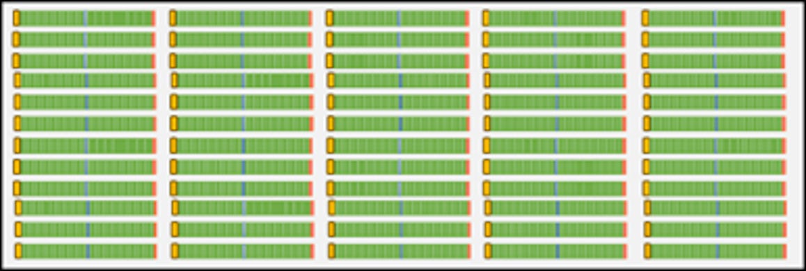
Each SHA-256 pipeline is a repetition of 64 stages which all have the same design, so the double-pipe repeats the base design 128 times.

This process is going on in parallel over billions of pipelines in millions of machines and will on average take 10 minutes for just one lucky pipeline to find a 68-bit zero prefix. The blockchain mining industry likely buys more than $1Bn of chips per year in pursuit of increasing efficiency as the difficulty rises. The number of zeros can be thought of as fractional, like 68.173 bits, continually adjusting to maintain an average 10-minute global pace.
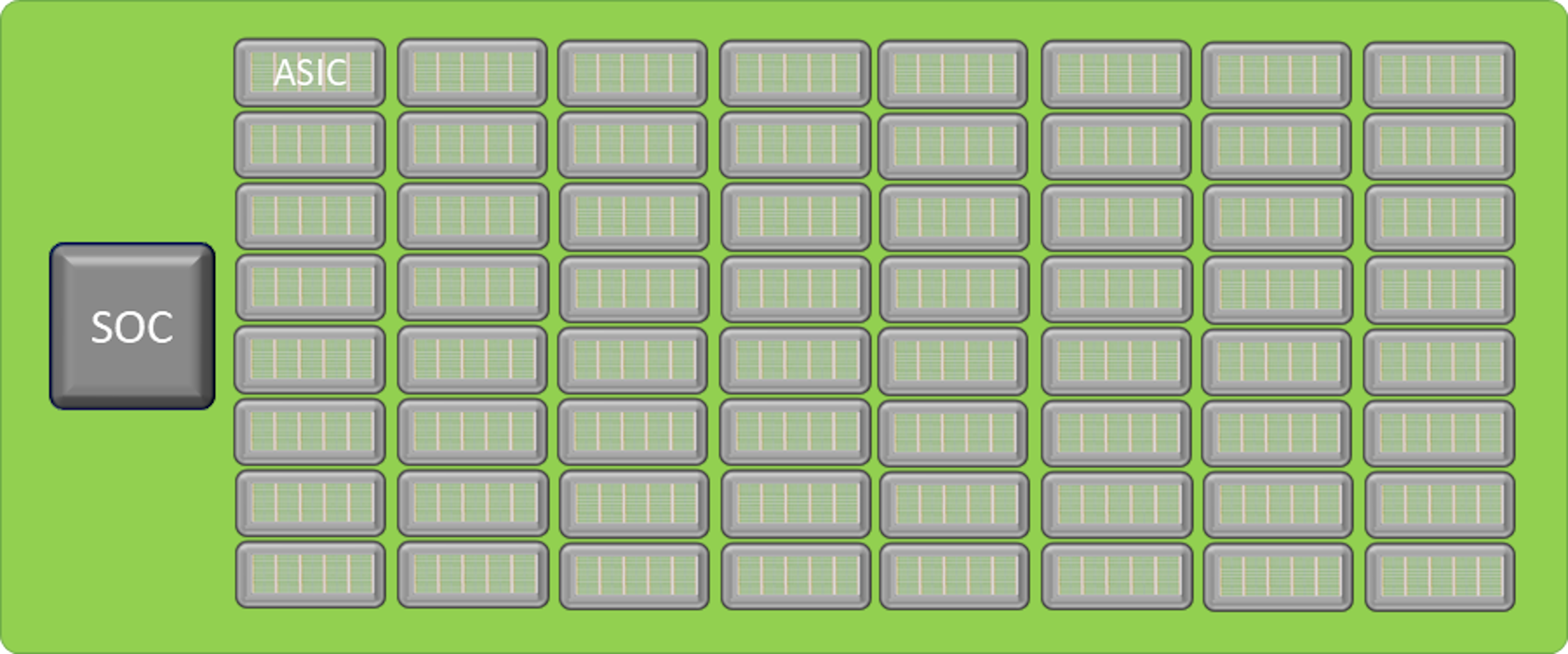
If you were keeping count, you would notice that SHA-256 pipeline needs to run 3 times - one for signing the transaction block, and then a double SHA-256 is used to hunt for the final value. That first block signature runs only once and then the remaining double SHA will run 4 billion times, so almost all the work happens in that double-SHA pipeline. The block signature can run efficiently enough in an ordinary CPU to keep thousands of double-SHA pipes busy with new prefixes. So, in practice a BlockChain ASIC only contains the logic for double-pipes, as well as the logic to initialize with a new prefix and to test the results and raise an alert if a lot of zeros are seen at the front. Everything else is handled by a standard SOC which will usually have both some ARM cores and an FPGA to help distribute the work to thousands of double-pipes using dozens of serial links, and to listen for alerts coming back.
This simplicity makes the miner pipeline stage a special case. It is repeated trillions of times around the world and consumes most of the 15GW of electricity used by the blockchain miners.
The Functions in One SHA-256 Stage
The SHA-256 stage is a combination of two parts called the digest and the scheduler. The digest never directly interacts with the message. The message is fed only into the scheduler. The scheduler handles a sliding window of 16 by 32-bit words of the message and it does a combination of recirculation and simple mixing of the 16 words. At each stage it writes one 32-bit mixed output over to the digest and loads another 32-bit word from the message to replace it. In the special case of the blockchain hash the entire message is 512 bits, which is to say 16 by 32-bit words, so nothing new actually comes in after the 16th word. This enables the scheduler to be simplified after 48 stages where none of the remaining mixing makes a difference to the words that will get passed to the digest.
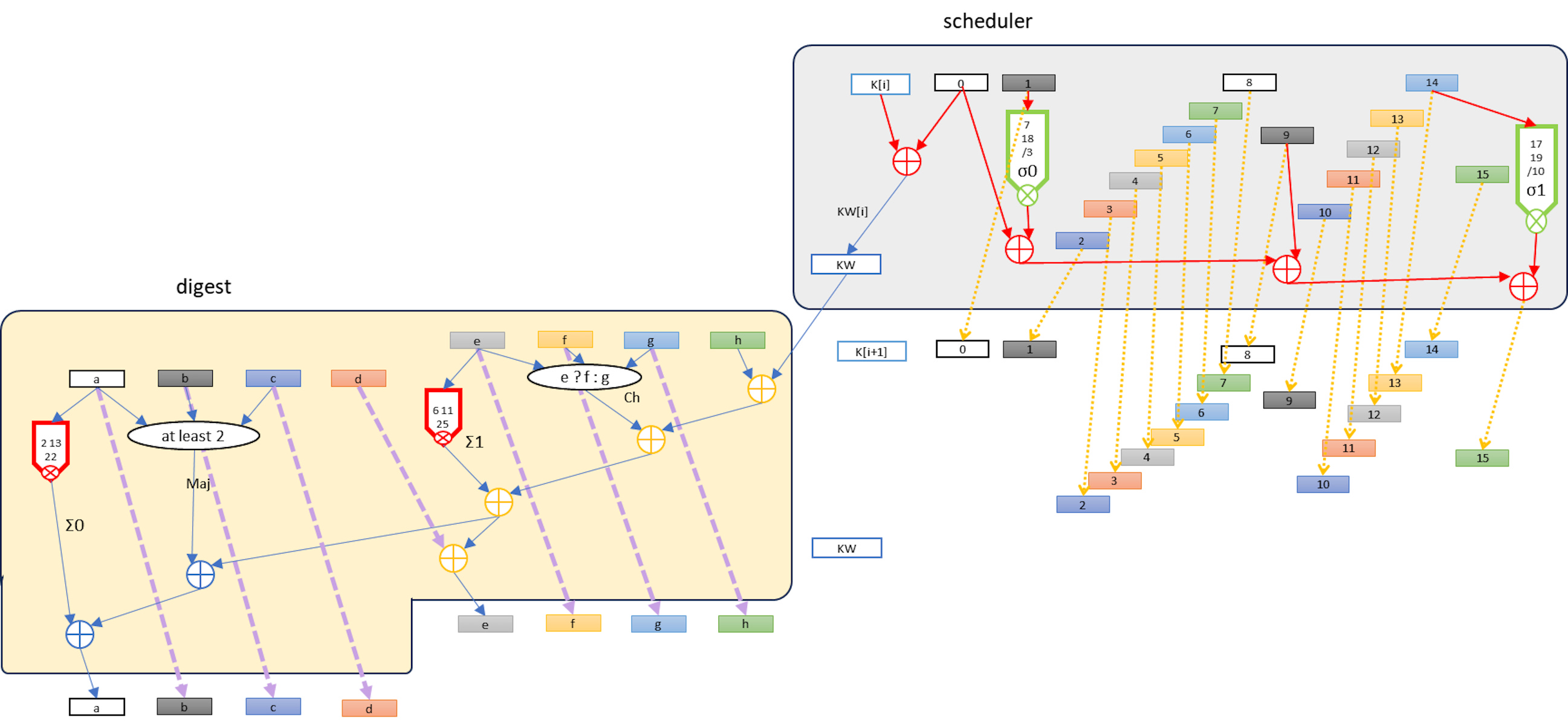
The scheduler and the digest operate at the same frequency, but the scheduler is not dependent on the digest. It passes the 32 bits per stage to the digest but nothing flows back from the digest to the scheduler so there is no round-trip latency constraint. The scheduler is a simpler design than the digest. The largest opportunity for saving energy is minimizing the energy used for clocking and latching, since most of the transistors in the scheduler are just being used for synchronized copy of unchanged values, from stage to stage just shifted over 32 bits. Only 2 of the 32-bit outputs from a scheduler stage are mixed, the other 14 are unchanged copies. There are 64 stages in each SHA-256 so the scheduler eventually makes a lot of changes, just not very much in any one stage.
I welcome discussion of the open section of the post, you can add comments to the Table of Contents for Pipeline post if SubStack will not allow your comments here. Thanks!
Thank you for supporting this blog.
Why is it a Pipeline?
I skipped past one detail, right at the start. Why use a pipeline with 128 stages, instead of using 128 copies of a 1-stage loop? They both do the same work, with 128 operations in progress either way, and probably at similar clock rates.
Mainly it is about reduced overhead. In the pipeline there is almost no overhead per stage, while with a loop design there is a copy of the setup and result logic around each loop, as well as multiplexing to change over from the initialization data to instead use the loop back from the output. True, that logic can be off much of the time so it does not draw power, but it does take up space. 128 single-loops would have 128 copies of the loop overheads instead of just 1 overhead per 128 piped stages.
There are some other advantages to the pipeline, too. The first and last few stages have some simplifications. At the start we are slowly mixing the scheduled message into some standardized constant inputs, which means that some of the calculations never change and a useful amount of logic can be removed and replaced by constant outputs. Then at the end we run out of new message scheduling so the scheduler can be simplified, and the test for 68 zeros can ignore about 190 bits of the result which also allows some logic to be skipped. Not huge, but useful.
Another advantage of the pipeline is that all the data flows in one direction. This avoids some crowding of the wiring which in the loop version has to go both forwards and backwards. These add up to a clear win for a straight pipeline of 128 stages.
The Digest Stage
I will be describing the design of the more complex digest logic, leaving the simpler design of the scheduler as an exercise for the reader. I do have the complete design, but it would not add anything to the educational purposes of this blog. The digest stage is more complex and provides a wider spectrum of challenges to be solved.

Each stage of the digest has 8 x 32-bit words of input (named “a” .. “h”) from a prior stage. There are some initializing pseudo-random constants in front of the first stage. Every stage gets a 32-bit “KW” input from the scheduler (a summation of a K constant, and a scheduled Word of the message). The longest latency chain would seem to be the chain of 5 adders beginning with KW input and ending with the “a” word output to the next stage. This is not quite what it seems if we look at the bit-level logic.
One Bit at a Time
The diagram can be read as a recipe for the individual bits a through h,
For each i in [31:0] for a[i] through h[i], and for KW[i]
which results in this logic for the ith bit as a bit-column of logic:

This column is designed to abut the neighboring column, with bit[0] on the right and bit[31] on the left. This is advantageous because there are only two full width additions needed, aSum and eSum at the output of the column. All the other adders are isolated full-adders (3 bits in and 2 out) which have no need of their own carry look-ahead. Instead the carries pass left and down to end up either in the aSum or eSum. Those are the only adders where we will need to consider how much overhead to spend on carry lookahead, and the two of them operate in parallel, not chaining their latency. In practice the latency of each of those adders will be 2 to 3x the latency of all the gates above, so they are the “long poles” we will eventually optimize.
Prioritize the Design Goals
Let’s take a step back and review the goals before we start choosing and placing the cells needed for the pipeline. The goals are:
1. Minimal energy per SHA-256 calculation
2. Minimal cost of the chip
3. Feasibility of using manual design to get a good estimate for size, energy, and speed
Minimizing energy per function is not the same as minimizing the “logical effort” of paths, which is probably the most widely used metric in ASIC design. The energy for a SHA-256 operation depends mostly upon the total capacitance of the circuits and the voltage for switching. If a node on a circuit has capacitance C (which is the sum from gates and wiring of that node) and the voltage change is V, then:
E = C V2 / 2
It may be surprising that resistance is not in the formula. Resistance changes the power but not energy of the switch. A low resistance switches fast for a high power, but the transition is completed briefly, while a high resistance runs at lower power over a longer time. So long as both modes run long enough to complete switching the same energy is used. We can also ignore leakage current in the SHA-256 case. The pipe is running at a high frequency and each transistor has about a 50% chance of state change (due to the pseudo-random function in all stages) so there are no idle nodes and deliberate switching dominates power and energy.
When it comes to the cost of the chip, that is when logical effect of paths becomes useful. Suppose we have a chip which can run at 500MHz with one design, but with careful redesign of some critical paths it would add 10% to size and energy per operation but run at 1GHz. This would add 10% to the electricity cost but remove 45% of the capital cost, since we would need only 55% of the size of silicon to get the same number of operations. We will try to get this kind of balance by first designing for minimum energy, then carefully adding silicon to optimize logical effort on the critical path which will allow a faster clock - but weighting the energy per operation weighted over speed, so only the least costly speed improvements will be accepted.
The feasibility of manual design is achieved by using a hierarchy beginning with the cell library and then the single bit-slice of the Digest. A single bit-slice is less than 30 cells, which we will lay out to support abutting so that 32 slices are easily aligned side by side to obtain a stage. A stage can abut the next so that 64 stages create a Digest pipe for SHA-256. We will then take a quick look at the initial, joining, and final logic of the dual-SHA pipeline to ensure those remain a very small proportion of the total size and energy load.
Again, a reminder that the double-SHA pipeline is a very special case. Very few other circuits have so many copies in use in the real world, and none of those are as simple and hierarchical as this one. This is an ideal example to try working through by hand.
Next week
Next week we compose a single bit column using cells from the library, laying them out and connecting them.